Iranian Classification Society Rules

< Previous | Contents | Next >
Section 3 Weld Design
![]()
Ch 2
301. Fillet welds
1. General
(1) Plans and specifications
The actual sizes of fillet welds are to be indicated on detail drawings or on a separate welding schedule and submitted for approval in each individual case.
(2) Workmanship
Completed welds are to be to the satisfaction of the attending Surveyor. The gaps between the faying surfaces of members being joined should be kept to a minimum. Where the opening be- tween members being joined exceeds 2 and is not greater than 5 , the welding size is to be increased by the amount of the opening. Where the opening between members is greater than 5 , corrective procedures are to be specially approved by the Surveyor.
(3) Special precautions
Special precaution such as the use of preheat or low-hydrogen electrodes may be required where small fillet are used to attach heavy plates or sections. When heavy sections are attached to rel- atively light plating, the weld size may be required to be modified.
2. Fillet welds
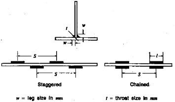
(1) Size of fillet welds
Fillet welds are
as required by equations.
generally to be formed by continuous or intermittent fillet welds on each side,
Table 2.l The leg size, w, of fillet welds is obtained from the following
Where 5. is applicable, min
where,
= the actual length of weld fillet, clear of crater, in
= the distance between successive weld fillets, from center to center, in
= 1.0 for continuous fillet welding
= thickness of the thinner of the two members being joined in
= weld factors given in Table 2.1
For the weld size for
less than 6.5 , see (6)
(2) Length and arrangement of fillet
Where an intermittent weld is permitted by Table 2.1, the length of each fillet weld is to be
not less than 75 for tpl of 7 or more, nor less than 65 for lesser
The unwelded length is to be not more than 32
(3) Intermittent welding at intersection
of 7 .
Where beams, stiffeners, frames, etc., are intermittently welded and pass through slotted girders,
shelves or stringers, there is to be a pair of matched intermittent welds on each side of each such intersection, and the beams, stiffeners and frames are to be efficiently attached to the gird- ers, shelves and stringers.
(4) Welding of longitudinal to plating
Welding of longitudinals to plating is to have double continuous welds at the ends and in way of transverses equal in length to depth of the longitudinal.
For deck longitudinals only, a matched pair of welds is required at the transverses.
(5) Stiffeners and webs to hatch covers
Unbracketed stiffeners and webs of hatch covers are to be welded continuously to the plating and to the face plate for a length at ends equal to the end depth of the member.
(6) Thin plating
For plating of 6.5 or less, the requirement of (1) may be modified as
Ch 2
![]()
The use of above equations for plating. in excess of 6.5 may be specially considered de- pending upon the location and quality control procedure of shipyards.
3. Fillet welds of end connections
Fillet welds of end connections where fillet welds are used are to have continuous welds on each side. In general, the leg sizes of the welds are to be in accordance with Table 2.1 for unbracketed end attachment, but in special cases where heavy members are attached to relatively light plating, the sizes may be modified.
4. Ends of unbracketed stiffeners
Unbracketed stiffeners of shell, watertight and oiltight bulkheads are to have double continuous welds for one-tenth of their length at each end. Unbracketed stiffeners of nontight structural bulk- heads, deckhouse sides and after ends are to have a pair of matched intermittent welds at each end.
5. Reduced weld size
Reduction in fillet weld sizes except for slab longitudinals of thickness greater than 25 may be specially approved by the Surveyor in accordance with either (1) or (2) provided the requirements of previous 2. are satisfied
(1) Controlled gaps
Where quality control facilitates working to a gap between members being attached of 1
or less, a reduction in fillet weld leg size of 0.5 may be permitted.
(2) Deep penetration weld
Where automatic double continuous fillet welding is used and quality control facilitates working to a gap between members being attached of 1 or less, a reduction in fillet weld leg size
of 1.5 may be permitted provided that the penetration at the root is at least 1.5 in- to the members being attached.
6. Lapped joints
Lapped joint are generally to have overlaps of not less width than twice the thinner plate thickness plus 25 .
(1) Overlapped end connections
Overlapped
both edges
end connections of main strength members are to have continuous fillet welds on each equal in size w to the thickness of the thinner of the two plates joined. All
other overlapped end connections are to have continuous welds on each edge of sizes w such that the sum of the two is not less than 1.5 times of the thickness of the thinner plate.
7. Plug weld or slot welds
Plug weld or slot. welds may be specially approved for particular applications. Where used in the
body of double and similar locations, such welds both directions.
8. Weld in tubular joints
may be spaced about 300 between centers in
The weld design of joint tower mooring is to be in
of intersecting tubular members which are used in fixed structure in a accordance with the Pt 2 of "Rules for Fixed Offshore Structures." ![]()
![]()
Table 2.1 Weld Factor
![]()
Ch 2
| ||
Periphery | Factor C | Welding method |
1. Periphery connection (1) Tight joints. (A) Main bulkhead to deck bottom or inner bottom (B) All other tight joints (a) watertight bulkhead ( < 12.5 ) - one side - other side (b) all other joints (2) Non-tight joints (A) Platform decks (B) Swash bulkheads in deep tanks (C) Non-tight bulkheads other than item b. | 0.42 0.58 0.12 0.35 0.28 0.20 0.15 | Double continuous Continuous Double continuous Double continuous |
2. Bottom floors. (1) To shell (2) To inner bottom (3) To main girders (4) To side shell and sulkheads (5) Open sloor bracket (A) to center girder (B) to margin plate | 0.20 0.20 0.30 0.35 0.15 0.30 | Double continuous Double continuous Double continuous Double continuous Double continuous |
3. Bottom girder (1) Center girder | 0.25 | |
4. Web frames, stringers, deck girder and deck transverses (1) To plating (A) in tanks (B) elsewhere (2) To face plates (A) face area 〈 64.5 (B) face area 〉64.5 (3) End attachment (A) unbracketed (see note 1) (B) bracketed | 0.20 0.15 0.12 0.15 0.55 0.40 | Double continuous Double continuous |
Ch 2
![]()
![]()
Table 2.1 Weld factor (continue)
Periphery | Factor C | Welding method |
5. Frams, beams and stiffeners (1) To shell (2) To plating elsewhere (3) End attachment (A) unbracketed (see nete 1) (B) bracketed | 0.25 0.12 0.45 0.35 | Double continuous Double continuous Double continuous |
6. Hatch covers (1) Oiltight joints (2) Watertight joints (A) outside (B) inside (3) Stiffeners and webs to plating and to face plate (see note 2) (4) Stiffeners and web to side plating or other stiffeners (A) unbracketed (see note 1) (B) bracket | 0.40 0.40 0.15 0.12 0.45 0.35 | Double continuous continuous Double continuous Double continuous |
7. Hatch coamings and ventilators. (1) To deck (A) at hatch corner (B) elsewhere (2) Coaming stays (A) to deck (B) to coaming | 0.45 0.25 0.20 0.15 | Double continuous Double continuous Double continuous Double continuous |
8. Foundations (1) Major equipment and auxiliaries | 0.40 | Double continuous |
Notes 1. The weld size is to be determined from the thickness of the member being attached. 2. Unbracketed stiffeners and webs of hatch covers are to be welded continuously to the plating and to the face plate for a length at ends equal to the end depth of the member. 3. With longitudinal framing the weld size is to be increased to give an equivalent weld area to that obtained Without cutouts for longitudinal. | ||